If you’ve been following this blog you already know that I’ve been working (for what seems like years, but was really just 10 months) on a new product, which I have named ‘Power*Star’. In my earlier posts I told you about the process of designing and manufacturing the product, and now that it’s almost ready to ship it’s time to tell you what Power*Star is all about.
The core functionality of Power*Star (abbreviated P*S) is quite simple: It provides a central distribution point for both the power (mostly 12VDC) and data (USB) typically needed for astrophotography. In the most basic implementation this core functionality could be provided with an off-the-shelf USB hub and a ‘splitter’ for the power connections. Putting it together in a box certainly makes it more convenient and attractive, but there’s a lot more that such a box could do for you, and Power*Star does it all.
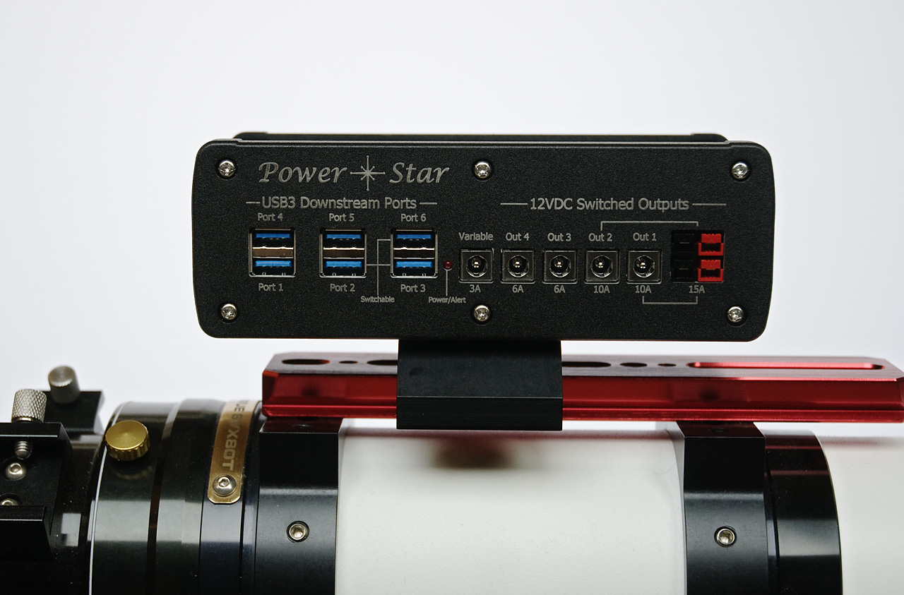
Let’s start with the USB hub, because that’s the least complex part of the design, conceptually. The hub in P*S is, for the most part, an independent unit that just needs power and a USB connection to your computer to operate. It provides 6 USB3 downstream ports from a single upstream connection. Each port supports both USB2 communications at up to 480Mbits per second, and USB3 communications at up to 5Gbits per second. 3 of the 6 downstream ports are ‘standard’ USB3 ports that are always ON and provide up to 0.9 amps of current (at 5VDC) to the connected device. The other 3 ports can provide up to 2 amps, and are switchable, meaning that under software control each port can be turned on or off. The hub chip inside P*S actually has 7 downstream ports. The 7th port is used to provide communication with the onboard processor in P*S. This processor is mostly involved with the power and other features of P*S, but does control the switchable downstream USB ports as well as a global reset of the USB hub.
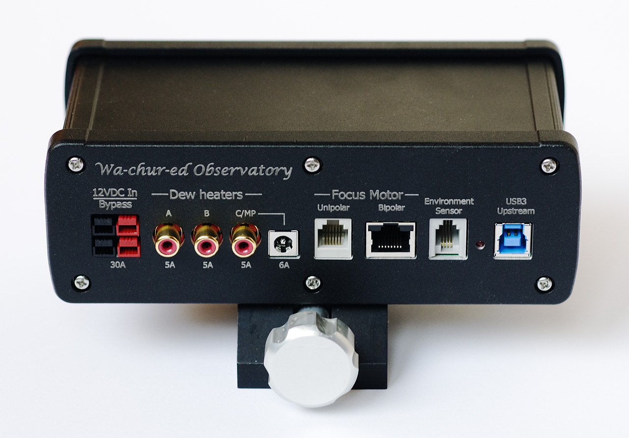
For the power section, P*S provides a wide range of control, monitoring, and protection features. It can handle a peak current level of 30 amps, although I recommend that continuous operation draw no more than 20 amps (most astrophotography systems will draw an average of well below 10 amps). The power input port (see photo below) uses Anderson PowerPole™ connectors to handle this level of current, and the unit comes with a power cable with mating connectors (the standard power cable is 14 gauge wire and 2 meters in length, but heavier gauges and other lengths are available for custom order). There are 2 PowerPole™ connectors on the input side, connected in parallel. These can be used as parallel inputs (allowing 2 power cables to provide more current and/or reduce voltage drop in the cables), or 1 can be the input while the other is an unswitched output (bypass) for an external device that must stay powered on at all times.
There are 4 ‘standard’ 12VDC output ports and 2 special power outputs (see the first photo above). Two of the four standard outputs can provide up to 15 amps of current and have both PowerPole™ and 5.5 x 2.1mm barrel connectors (the defacto standard for astronomy gear). The other two standard power outputs, and both of the special purpose outputs use the barrel connector only. All of the barrel connectors are of much better quality than the typical plastic parts used in most equipment (including some very expensive astro cameras!). The outer barrel contact is made by multiple spring ‘fingers’ that grip the barrel tightly. I could have used connectors with a threaded collar, but this type provides nearly as solid a connection without the hassles of threading the collar. These barrel connectors are rated for 10 amps, so the high power outputs (ports 1 and 2) are derated from 15 amps to 10 when using the barrel connector instead of the PowerPole™ connector. The other outputs are limited to 6 amps due to the capacity of the internal circuitry. This is more than adequate for almost all astro gear, so one need only select the appropriate output port to handle just about anything that might come up – now or in the future.
One of the ‘special’ outputs is a variable voltage output that can be adjusted to any voltage between 3V and 10V in 0.1V increments. The current limit for this output is 3 amps. This output is typically used to power a DSLR camera at 8VDC, but it can also be set to 5V to power a local processor, for example. The voltage is locked and cannot be changed while the output is turned on.
The other special output is referred to as the ‘multi-purpose’ output, having 3 distinct functions: It can be a standard 12VDC output (with the same specifications as outputs 3 and 4), a dew heater channel (more on that below), or a ‘fast PWM’ output. PWM (for Pulse Width Modulation) is commonly used to control devices where reducing the voltage provides a useful control function. For example, the speed of a fan or the brightness of a light source can be changed under software control. It does not actually change the voltage (as the variable voltage output does), but rapidly switches the 12V power on and off for a controlled period of time. This works for some devices, but not all. Dew heaters are one example of a device that can be effectively controlled via PWM. Many competitive products provide PWM outputs and suggest that they can be used for multiple purposes, including dew heaters. P*S makes a distinction between dew heaters and other PWM-controlled devices by the speed of the PWM (the switching frequency). Specifically, dew heaters can take a large amount of current, but do not need to be switched frequently, since the heat they generate is transferred very gradually to the telescope. Using a high frequency switch for a dew heater can produce electro-magnetic interference (EMI), noise that can leak into sensitive electronics such as cameras. P*S uses a switching frequency of just 1 cycle per second for dew heaters to minimize EMI and maximize efficiency. The ‘fast’ PWM output, on the other hand, needs to be fast enough that the on/off switching is not apparent to connected devices. For example, a common use for the PWM output is to drive a ‘light box’ that is used in capturing flat calibration frames. But if the switching is too slow it can severely limit the range of shutter speeds that can be used, since there is no synchronization between the on/off cycling and the camera’s shutter. P*S uses a 2kHz (2,000 cycles per second) switching speed for the PWM output. It also provides 1024 levels, while the dew heater outputs operate from 0 to 100% in 1% increments. The multi-purpose output has both a barrel connector and the defacto standard RCA jack for dew heaters, connected in parallel.
Each of the power outputs is switchable under software control, and each is monitored to provide information on the current draw (except the variable voltage output, which instead provides a voltage measurement). These measurements are also monitored by the onboard processor to ensure that safe limits are not exceeded. This begins what could be a very long discussion of safety features in P*S, most of which involve electrical power. Instead of boring you with a lot of details, I will just list the most important safety features:
- Reverse polarity protection (if input power is connected with incorrect polarity it is blocked from all internal and downstream connections, except the ‘pass-through’ 12VDC connector at the input)
- Electro-Static Discharge protection (typical levels of static discharge and other transient voltages will not damage P*S)
- Input voltage protection (the outputs will be turned off if the input voltage is either too low or too high for safe operation)
- Over current protection (the total current draw is monitored, and all outputs will be turned off if the safe limit is exceeded)
- Per-port current protection (each individual port is monitored, and will be turned off if its current limit is exceeded)
- Internal protections (various voltages and other fault conditions are detected and handled appropriately, including motor faults)
In most cases there are 2 levels of fault detection: The first level is user-settable and is typically just a warning, although in many cases the user can choose to have the affected port turn off on a first-level fault. The second level of fault is defined by the hardware capabilities and is not alterable. In many cases there are both software-based detection of faults and hardware features that prevent damage to both internal circuitry and the external equipment connected to P*S. Some second level faults (those not limited to a specific output) are considered fatal faults, which result in a complete shutdown of the P*S system. When a fatal fault happens (which is rare, unless you are trying to make it happen) the event is reported to the user with information to help you fix the problem before starting up again. The event is also remembered in most cases so that at the next start-up all outputs will be initialized to OFF until the user confirms that the problem has been resolved (normally, the user can specify whether each output should be on or off at start-up).
There are three other functions that are typically needed at the telescope; dew heater control, focus control, and environment (temperature and humidity) monitoring. All of these are integrated into P*S so that no other control devices are typically needed. I’ve already mentioned the dew heaters. There are 2 permanent dew heater channels, and the multi-purpose output can be configured as a 3rd dew heater channel. There are 3 RCA jacks, 1 for each channel. The RCA jack is the defacto standard for dew heater connections, but is actually a very poor choice for this purpose. RCA jacks and plugs are intended for low-level audio applications, not for power. Most RCA connectors do not even specify what their current and voltage limits are, since that is irrelevant for the intended applications. P*S uses the best RCA jacks we could find, but we still recommend limiting the current to 5 amps. Slightly more current (6 amps) can be had using the barrel connector of the multi-purpose output. Most dew heater straps come with fairly low quality RCA plugs as well, and we suggest replacing these with a better quality plug (available from Wa-chur-ed).
The focus controller in P*S is built around the PerfectStar and PerfectStar B controllers, and provides separate outputs (and driver ICs) for bipolar and unipolar stepper motors. It is not a true dual channel controller, but it is fairly easy to switch between one motor and the other. Most competitors use a single driver IC for both motor types. This can be made to work, but it does not provide the optimum drive characteristics for both types of motor, and does not allow two motors to be connected simultaneously. The setup parameters for both types of motor are similar to what is provided in PerfectStar and PerfectStar B, but is more generalized so that P*S can be used to drive a wide variety of motors. The drive current for both idle (braking current) and moving can be set by the user, as well as the step period (speed). The P*S application includes presets for motor configuration, with defaults for typical focus motors as well as selections for user-defined motors.
P*S comes with an environment sensor that is meant to be placed away from the controller itself, in a location that provides free movement of air. It provides accurate temperature and humidity information, and the P*S application calculates the corresponding dew point. The application provides automatic dew control using this information: The user specifies a trigger point (the difference between ambient temperature and dew point), and the power level for each dew heater channel. The system then turns the selected channels on or off according to the settings.
The P*S application for Windows platforms is a fairly large topic itself, so I will leave that for another time. There are also ASCOM drivers to provide access to the focus controller and environment data to third-party applications. There will also be INDI drivers and Linux-based software to control P*S, but that is from a third party, and not directly provided or supported by Wa-chur-ed.
In the picture below you see Power*Star mounted on top of the ‘scope with the included universal dovetail saddle. It is connected to a tiny computer (with no display) that sits on a shelf at the base of the mount:
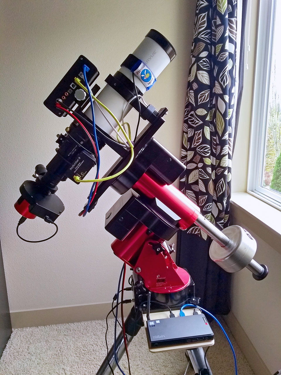
The connections, from left to right, are: 12VDC input, Dew heater, (unused outputs), bipolar focus motor, environment sensor, and USB upstream connection. Not visible on the other side are USB connections to the imaging camera and guide camera, and a power connection to the imaging camera. The filter wheel connects to USB through the camera.
Power*Star will be available soon, but initial quantities are quite limited and I’m not sure when more will be available. The list price is $550, which includes the universal saddle, power cable, and environment sensor. Custom configurations are available (including removal of the saddle), and are individually priced. A variety of options are available, including several adapters to different kinds of power connectors.
The name ‘Power*Star’ maintains some continuity with the PerfectStar family of focus controllers, but emphasizes the power control and monitoring features. The asterisk in the name is a textual way of representing the symbol used in the logo:
![]()
This symbol is meant to represent both an actual star (with diffraction spikes), and a ‘star’ network configuration, with network nodes represented by the dots at the ends of the diffraction spikes. Power*Star is now at the center of my imaging system, where it will greatly simplify and improve the process of capturing images. I hope you will find it useful as well!