
This is part 2a because I had intended to be finished now (Part 2), but that didn’t happen. I have good excuses! While waiting for the concrete to set I got Covid. This was the first time for me, and I was very cautious about it – staying in quarantine pretty much full time for 5 days. I’m feeling much better now, but my strength is returning slowly. And now it has started raining, so it will probably be a few days before I can do any more work.
The first step after allowing the concrete to set was to remove the frame that held the pier supports in place:
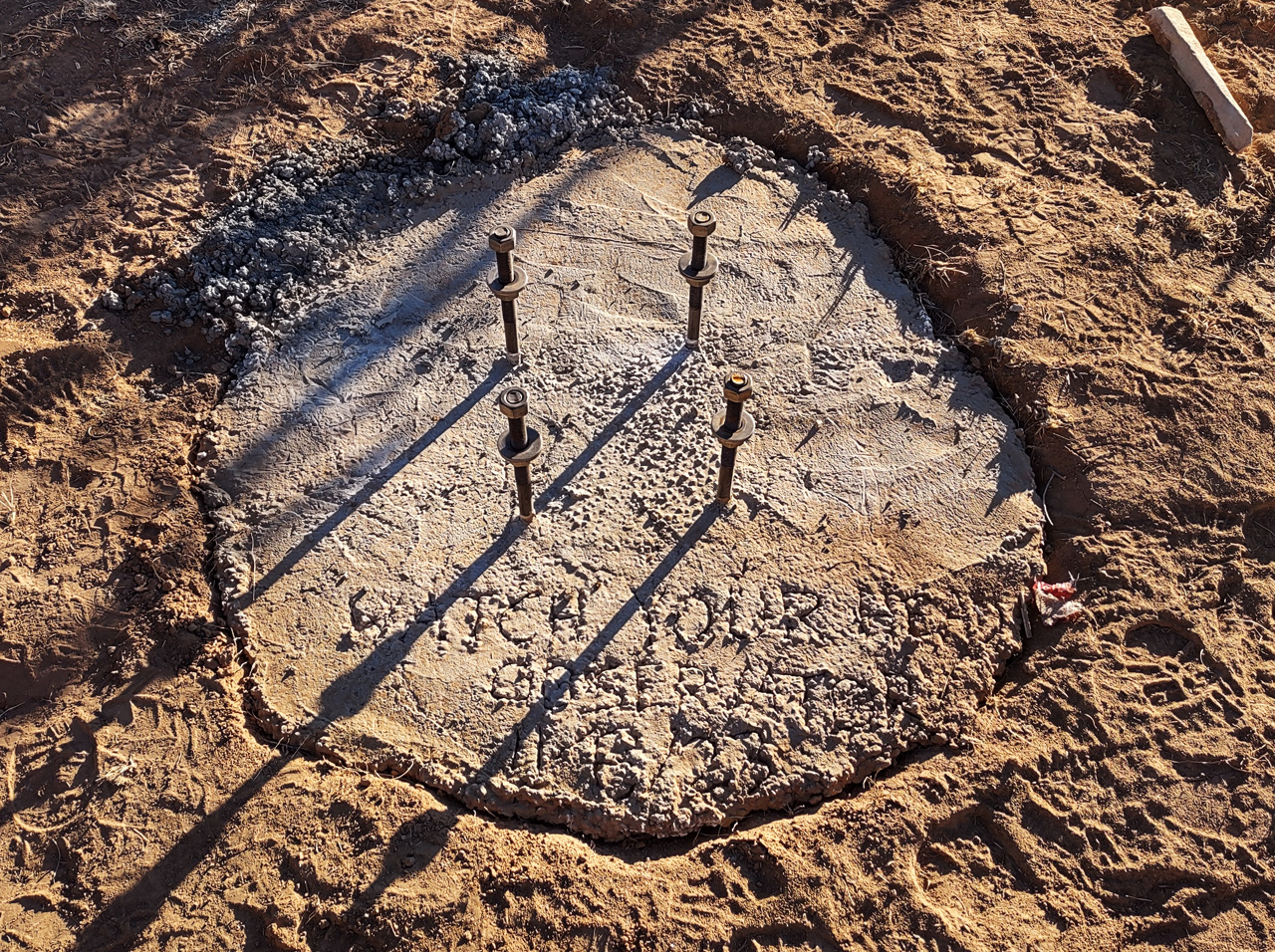
I had scratched “Watch Your Head Observatory” and the date in the concrete, but it’s barely legible in this light. The purpose was just for documentation – it’s quite possible that no one will ever see this.
The next step should have been to place the pier on its support. In reality, I did this later because I didn’t have a way to move the thing (it’s very heavy), but I’ll show it here as if it were done in the right order:
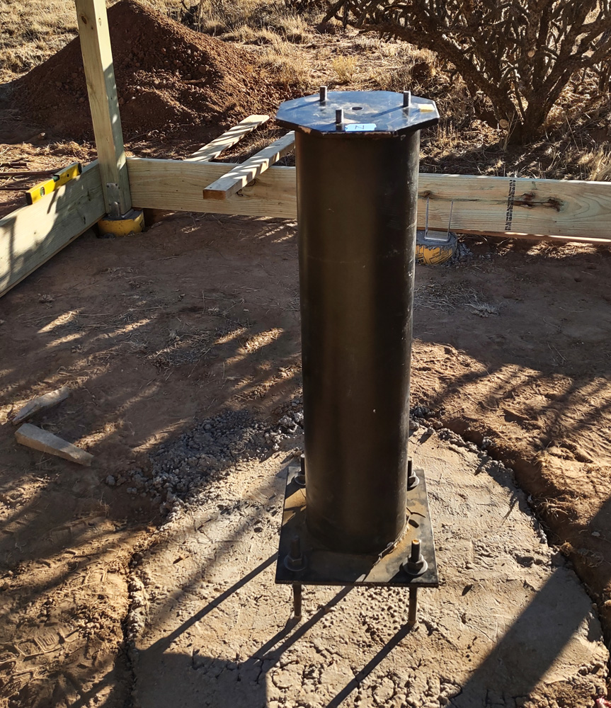
The pier is an 8″ steel pipe with steel plates at each end. I did a rough alignment to make the pier straight up, but this will be fine-tuned later when the top pier plate is in place, since that is the real and proper reference point.
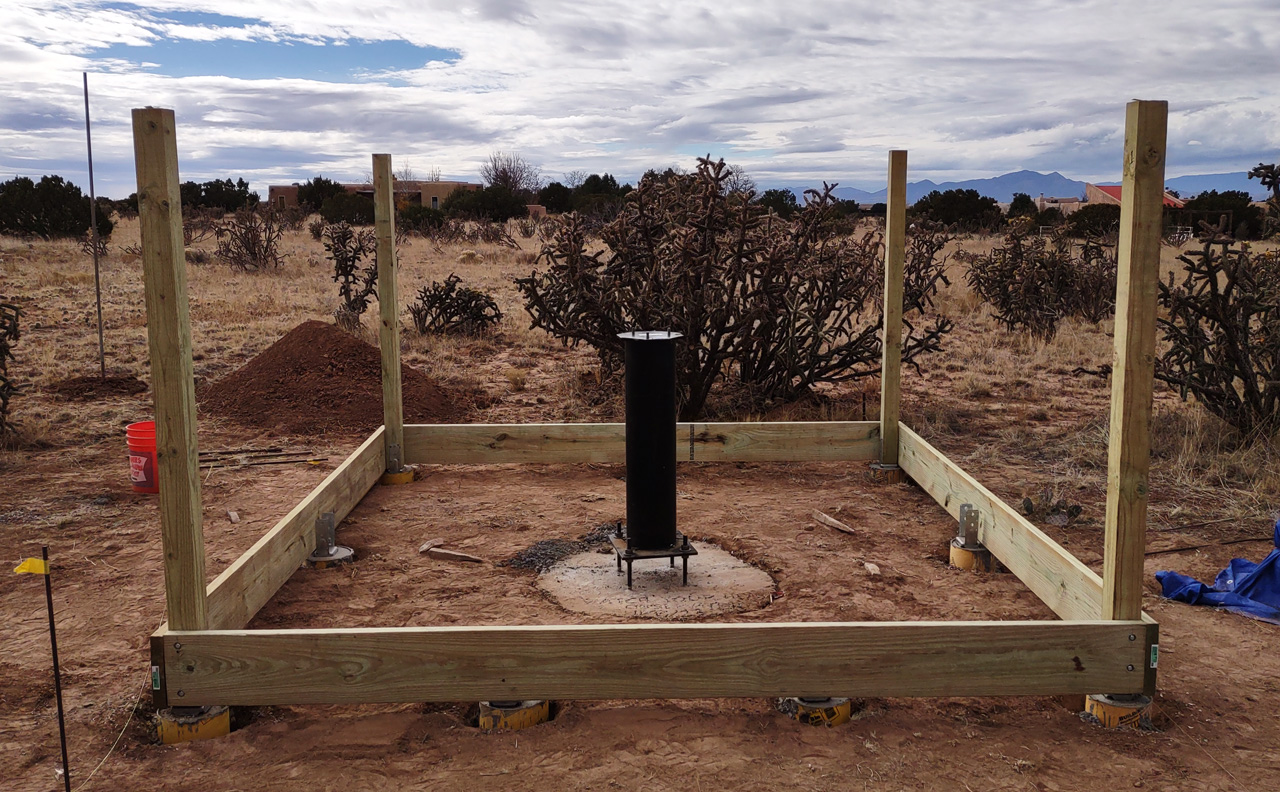
Next, the 4 corner posts were attached to the footings:

The horizontal boards across pairs of posts was just to provide some stability. The metal pieces that are embedded in the concrete are made to fit snugly around the posts, and allow adjustment of the position in only one axis (X or Y), so I arrange them such that each pair of posts could be adjusted at one end to have exactly the right distance between them (although the “squareness” would be thrown off slightly). The in-between posts are all adjustable in the “in-out” axis, since getting them perfectly centered is not critical.
With all the corner posts in place the “skirt boards” could be attached:
The objective in this step is to get all four boards level and meeting each other at the corners. It helped a lot that we leveled the footings while pouring the concrete, but there is always some shrinkage as concrete sets, and it wasn’t exactly the same at each footing, so a little tweaking with shims was necessary. Later, joist boards will go across the left and right sides, then deck boards will run the other way, with the top surface flush with the skirt boards.
Finally, the remaining posts were placed:
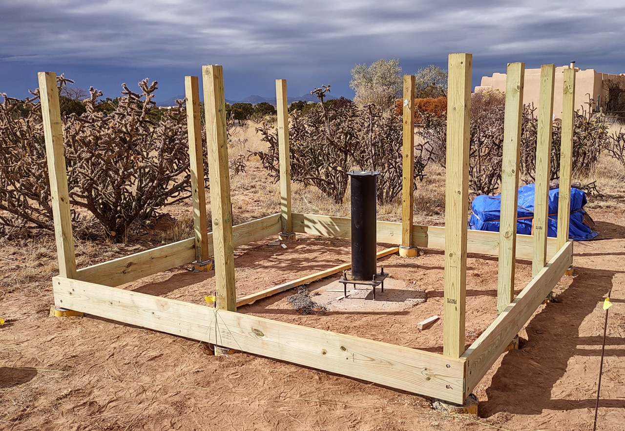
Since three of the four skirt boards were bowed in or out, I used the corner posts as the reference to determine the correct position for each of the in-between posts. Then it was just a matter of getting each post pointing straight up. I found this to be difficult to do by myself, but it’s easy for a helper (my wife) to hold a post in place while I drive the screws that secure it in place.
While I was recuperating I also spent some time preparing my “big ‘scope” (the William Optics FLT-132) to be installed. I had to buy and install new narrowband filters, as I have been using my old filters that are not quite big enough for the larger sensor in the QHY268m camera. While working on this it occurred to me that it’s not entirely clear which end of this telescope should be considered the “business end”. The front part contains most of the optics, and does the all important job of collecting photons and bringing the image to focus on the sensor, but that’s a relatively simple job. The back end is much more complicated:
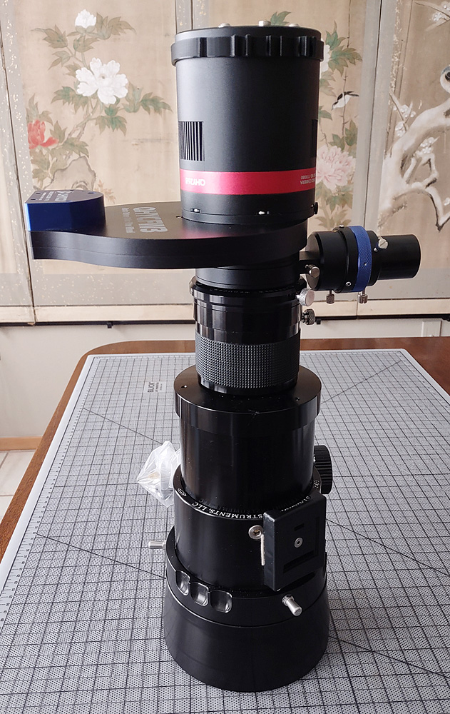
The bottom half of this “stack” is the focuser, a 3.5″ (ID) FeatherTouch. Conceptually, adjusting focus is very simple, but it’s actually very demanding of a mechanical device to move in and out (Y axis) without the slightest deviation in X or Y, or rotation. It’s even more difficult when you have a heavy camera and a bunch of other stuff hanging off the end of the focuser. To achieve focus automation it also has to move in/out without slipping. I have worked with many different focusers, and found that only the FeatherTouch meets all these requirements.
Above the focuser (behind it, if you think about it in terms of the light path) is an optical device called a “reducer/flattener”, which compensates for the primary optics being designed for visual use rather than photography. It also “reduces” the effective focal length and focal ratio to provide more light on the sensor and a slightly wider field of view.
Above that you will see a device sticking out to the right. This sub-system is called an “off-axis guider” or OAG. It contains a small prism that takes a little bit of the light near the edge of the field and sends it off to the side, where a special camera can take relatively short exposures that are sent to a computer for analysis. The software effectively watches the position of stars in this sub-field image, and sends commands to the mount to make small corrections in the pointing angle, thus keeping the image stable.
Next up is the filter wheel, which sticks out to the left. As the name suggests, this contains a set of optical filters (7 of them, in this case) mounted in a wheel that is rotated by a small motor to place the desired filter in the optical path. These filters are quite small and not terribly impressive to look at, but they are extremely high tech, and priced accordingly, especially the narrowband filters I added recently. The 7 seven filters together account for the greatest part of the expense of the whole system, including the telescope. My friends and family in Vermont might be interested to know that these filters are manufactured by a company called Chroma Technology, in Bellows Falls, VT.
Finally, the end of the image path is the camera, the QHY268m. As modern digital cameras go, I suppose this is not very impressive. It’s resolution is 26Mpixels, and the sensor is APS size – the same as most DSLR cameras. A few things make it different from a DSLR: It is monochrome, which allows greater flexibility in using filters (and improves image sharpness by avoiding the need for a color filter array (Bayer array). The electronics are probably better than what you will find in a DSLR, being designed to yield the lowest possible noise. And the camera contains a thermo-electric cooler to further reduce noise. I normally run the camera at -5C in the Summer and -15C in the Winter.
All of the above will be attached to the back end of the telescope, which then attaches to a Paramount MyT mount to allow it to point anywhere in the sky and accurately “track” the motion of the sky. The mount attaches to the top of the pier shown above, which is anchored in a cubic yard of concrete.
I don’t know which should be considered the “business end” of this optical system, and both are pretty interesting, but the back end is clearly more complicated.