One of the most valuable features of Power*Star is something you might never have to deal with, its fault detection and protection system.
The first protection mechanism is the reverse polarity protection. When the input voltage is connected “backwards” (with reversed polarity) a large power transistor blocks the voltage from reaching either the internal circuitry or the connected devices. This can easily save you from a very expensive mistake, although when using the standard PowerPole connectors at both ends of the cable and a (carefully) prewired power source, there is very little chance of it ever happening. The only downside is that the power transistor does add a small amount of resistance to the path, which results in a small voltage drop when drawing a lot of current (there is an option to bypass this protection if the small voltage drop is more important).
It’s important to keep this protection in mind because there is no positive indication of the fault – the system simply does not power up. Also note that this protection does NOT apply to the “pass-through” power connector, which is just connected in parallel with the input.
One other protection that is independent of system operation is the transient voltage protection. Brief voltage excursions, either positive or negative, are absorbed by TVS (transient voltage suppression) diodes. This is primarily a protection for the input voltage, but there are also varying degrees of suppression for other ports (input and output). As is always the case with TVS systems, there is a limit to how much energy a diode can absorb, so transients should be avoided as much as possible. For example, you definitely don’t want the system to be hit by lightning!
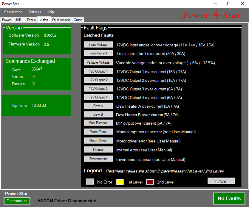
But the real heart of the active protection system is what you see in the Status and Fault Action tabs of the P*S app. The status tab (see image above) shows the state of 14 separate fault conditions that are continuously monitored by the P*S processor. Some of the items actually cover more than one fault condition, such as the over-/under-voltage faults. Each of the 14 items has a color coded button for quick identification. Under normal conditions each button will be gray. In most cases, each item has 2 levels of fault, corresponding to “warning” and “critical” faults. First level (warning) faults are indicated by a yellow button, while second level (critical) faults are shown in red. Note that the red color used is not very bright, which seems inconsistent with the critical nature of the fault, but we found this to be necessary to be able to clearly distinguish between yellow and red when using a red filter over the screen, as is often the case. Once a fault condition is removed or goes away on its own, the fault can be reset by clicking the Clear button in the lower right corner of the status tab.
Notice that when any fault has been triggered the global fault indicator in the lower right corner of every tab will show it, so it is visible at all times that the app is visible. When the app has been minimized or is obscured by other apps, a pop-up warning plus an audible alarm may appear (always for second level faults, selectable for first level faults). This indicator stays active until all faults are cleared. That is, even momentary faults trigger the fault system and the indicators stay active until cleared, even though the fault condition has ended. This is done so that if a fault happens while you are not watching the app, you will still know that it happened.
The Fault Actions tab lists the same 14 faults, and allows you to set the first level fault trigger levels, and what action the system should take when a fault is detected.
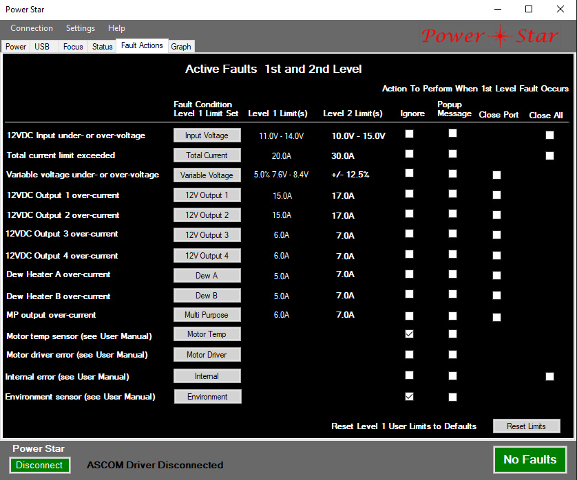
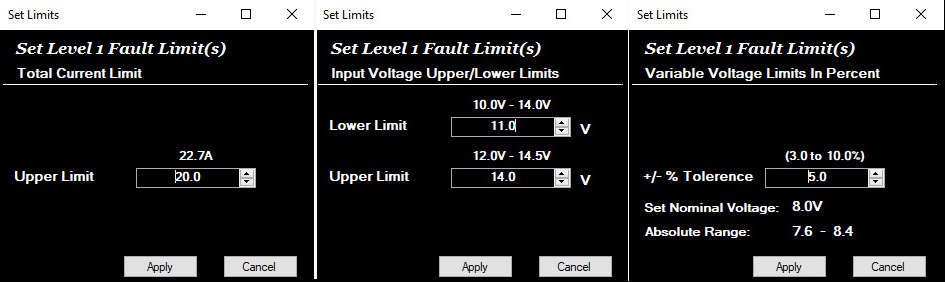
Next to each fault description is a button. When one of these buttons is clicked it will (for most fault types) pop up a menu that lets you set the level you want for first level (warning) detection. For the total current and per-port current faults there is a single parameter, the upper limit in amps. When a current level above this value (but less than the second level fault value) is detected, a first level fault is triggered. For the input voltage level both upper and lower levels can be set. For the variable voltage output the level is specified as a percentage rather than an absolute voltage. This allows you to change the output voltage without having to redefine the fault levels (the P*S system calculates them for you using the percentage parameter). The lower 4 fault conditions do not have trigger levels, but are simple yes/no triggers. Clicking the button for one of these faults does nothing.
The first level fault triggers can be used to generate a warning when conditions fall outside normal operation. For example, after observing the current draw for a particular device, you could set the trigger level to be a bit higher than the typical peak. !0% higher might be a good starting point. This can provide an early warning when something is abnormal, but not yet critical. The default levels for these triggers are near the maximums, so that for most situations it is not necessary to set different levels at all.
Second level (critical) fault triggers are pre-defined and represent the hardware limitations that cannot be safely exceeded. When a second level fault occurs the system takes whatever action it can to protect the system. For per-port current faults (or voltage fault for the variable voltage output) the offending port is turned off. For total current and input voltage faults all outputs are turned off. Note that the over-voltage critical fault will typically protect the connected devices, but it cannot disconnect the input voltage from the internal circuitry, so it is important not to connect an excessively high voltage source. While 15V is a good number to use as a guide, the system should withstand at least 18V without damage.
For each fault type there are two or three checkboxes that determine what action the system will take when a first level fault is detected. The first column of checkboxes is “ignore”, meaning that no action is taken. While it is preferable to adjust the trigger levels to avoid faults that you don’t care about, the “ignore” checkbox is a quick and convenient way to fix a recurring first level fault. Two of the faults that do not have trigger levels (Motor temperature sensor and environment sensor faults) are set to “ignore” by default since these are typically very unimportant conditions. In fact, the Motor Temperature Sensor fault will always be triggered if you do not have a supported motor type connected. First level faults for either of these sensors usually just means that there was a temporary communication interruption with the sensor.
The second column of checkboxes can be used to enable a pop-up warning message when the corresponding fault is detected. This can be useful in debugging a system to determine when a fault is triggered. The third and fourth checkboxes can be used to close (turn off) either the affected port (for per-port conditions) or all ports (for global conditions). These are usually not needed, but could be used, for example, to protect a 5V device connected to the variable voltage output from excessive voltage.
Note that both first and second level fault triggers are somewhat “filtered” to avoid spurious triggers. Second level trigger filtering is minimal to provide the fastest possible response. The worst case delay for first level fault detection is about half a second.
All first level trigger levels can be reset to factory default levels by clicking the Reset Limits button in the lower right corner of the Fault Actions tab.
When setting the first level fault trigger level for total current you will find that the maximum accepted level is 22.7 amps rather than the 30 amps you might expect. While we recommend a maximum of 20 amps continuous current, the trigger level is actually limited to 22.7 simply because of limitations in the internal representation of the value in software. If you really need more than 22.7 amps peak (and have taken other precautions such as using heavier input power cabling to minimize voltage drop) you can check the “ignore” box for this fault. The second level fault detection will still trigger at 30 amps.
A common question is what minimum voltage level is appropriate when running off batteries. There are a lot of different numbers suggested for 12V lead-acid batteries, ranging from 10V to 12V. To a large degree it depends on whether your priority is maximizing the life of your batteries or getting as much imaging time as possible. What makes it really complicated is that the voltage will vary tremendously with the load, and thus have little correlation with the remaining charge capacity of the battery. A much better way to gauge battery capacity is to use the Total Amp-Hour value displayed in the Power tab. But you might also want to set a lower limit to define the minimum voltage at which your connected equipment will operate properly. Most astro gear is not particularly sensitive to the 12V voltage. For heaters and thermo-electric coolers (TEC) the voltage may impact the ability to heat or cool, but this is usually not a hard failure. Other types of batteries will have different upper and lower voltage properties, so please consult the manufacturer’s guidance in such cases.