To properly process an astrophoto the first step in most cases is ‘calibration’. The purpose of calibration is to compensate for various defects in the image sensor and the optical system. Essentially, we capture images that isolate the most common defects and mathematically apply the inverse of the error to each of the raw images we have captured. One part of this calibration is to remove unevenness in the brightness across the frame. This step is called ‘flat calibration’. Unevenness (lack of flatness) can be caused by vignetting of light by the optical system (the image is darker in the corners than in the center), by the existence of dust particles on filters or on the image sensor itself, and by variations in the response of each photosite/pixel (how large a signal is produced in response to a given amount of light). To restore flatness to the image we capture an image of a perfectly flat, white field, using the same optical system, filters, and camera. The actual astrophoto images (called ‘light frames’) are then divided by the flat frame to produce a flat-calibrated image. That is, the value of each pixel in the light frame is divided by the value of the corresponding pixel in the flat calibration frame.
For example, here’s a (simulated) raw exposure of the Horsehead Nebula:
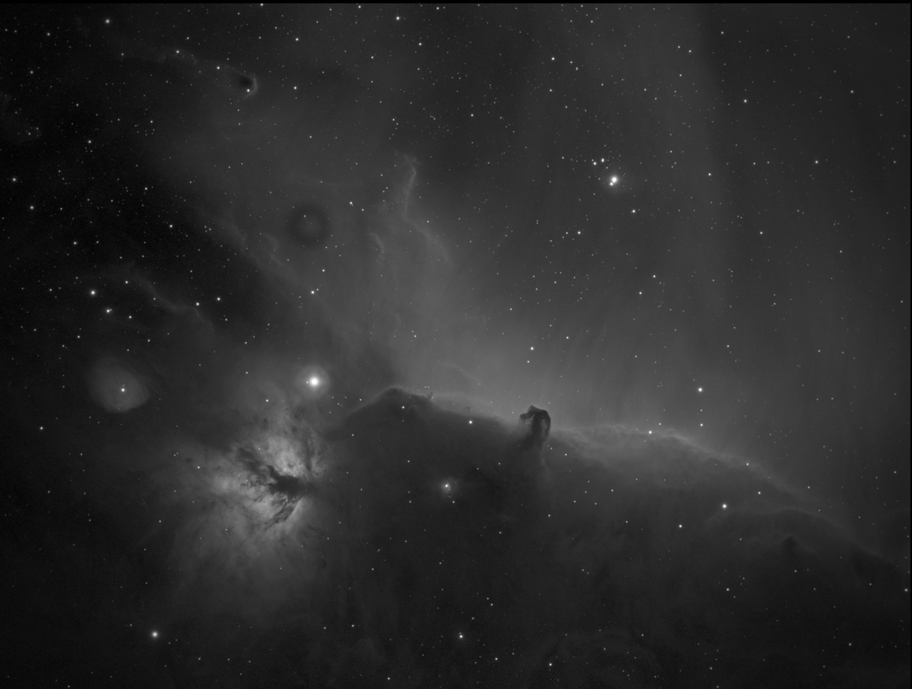
It doesn’t look horrible, but there are some defects that can be removed (often times the appearance of the raw frame is much worse and really needs flat calibration). Below is a ‘flat calibration frame’ (simulated) captured with the same telescope, filter, and camera:
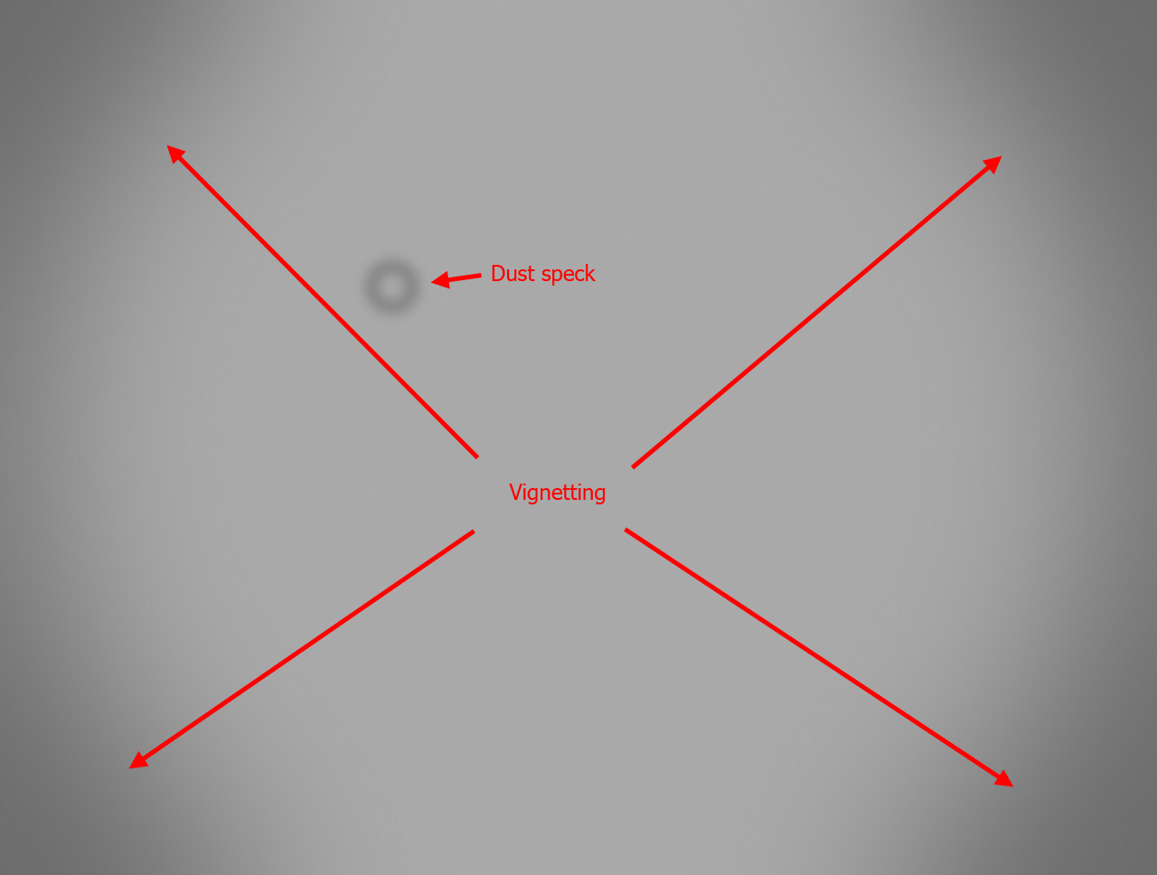
This makes it easy to see the defects. The ‘donut’ shape is caused by a dust speck and is very typical. In fact, you can identify the location of the speck by measuring the diameter of the donut. In this case it is likely on the filter.
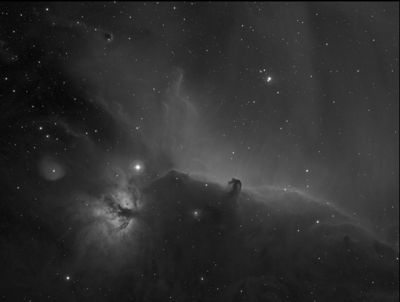
When the raw frame is calibrated using the flat frame, the defects are removed:
There are many ways to capture flat frames, and each has its own advantages and drawbacks. For example, perhaps the most accurate flat frames are created by photographing a clear sky at twilight, when the brightness is just right. Special techniques must be used to ensure that there is no brightness gradient across the frame and that stars do not impact the final flat calibration frame. When done properly, these ‘twilight sky flats’ are excellent, but it can be a real challenge to capture them properly. A much more popular technique is to use a flat light source that is relatively close to the telescope – often placed right in front of the ‘scope, resting on the dew shield. With such a light source flat frames can be captured at any time, using quite short exposures.
The most commonly used type of light source is the electroluminescent panel (EL panel). EL panels are inherently pretty even in brightness across the surface, although not perfect. They are also very light weight, which allows them to be used in systems that mount the panel on the telescope with a motor that allows the user to remotely control whether the EL panel is placed in front of the ‘scope or out of the light path. However, EL panels require a high voltage AC power source, typically in the form of an inverter powered by 12VDC. Variations in the voltage and frequency of the inverter output affect both the brightness and the color of the EL panel. I used to sell a flat light source based on EL panels, but had to discontinue it due to supply issues with the panels.
Another technology that is sometimes used as a flat light source is based on LEDs. Rather than using a large array of LEDs pointing directly into the telescope (with a suitable diffuser between them), most LED panels use an acrylic ‘light pipe’: A string of LEDs is placed around the edges of an acrylic sheet with a white reflector behind it. This is how liquid crystal displays (LCDs) are usually illuminated, and not so coincidentally, how I used to illuminate my backlit film prints, back when I was selling such prints.
Edge-lit LED panels are NOT inherently even in brightness, tending to be much brighter around the edges, where the LEDs are close by. A special type of acrylic material is available that helps a lot to flatten the brightness, but it is designed to be only flat enough for things like signs – and backlit astrophotos. However, there are multiple techniques that can be used to further flatten the brightness. When done carefully, the brightness can be more even than a typical EL panel.
Another consideration with flat light sources is the color of the light. Both EL panels and LEDs are not true ‘broadband’ light sources, but produce light at multiple wavelengths that, when combined properly, appear as white to the eye, but not necessarily to a camera. In the case of EL panels, this is part of the supply issue I mentioned: Because EL panels have a relatively small market, there is far less choice of color scheme. LEDs can be and are made with a huge variety of colors, including devices that have 2 or 3 different colors (such as red, green, and blue) in a single device. An RGB LED can appear as white, and can work quite well with some camera/filter combinations. However, the vast majority of so-called ‘white LEDs’ are actually made by surrounding a blue LED with a yellow phosphor. The (narrowband) blue light excites the phosphor, which then radiates a broad spectrum covering the green and red bands. Some of the narrowband blue light gets through the phosphor also, so you get a ‘white’ light that is a combination of a narrow blue and a broad green/red. The specific phosphor chemistry can be adjusted to balance the broadband output, and to adjust the amount of blue that passes through the phosphor. Therefore, you can buy white LEDs of almost any white balance you want, as well as varying color rendering indices (CRI).
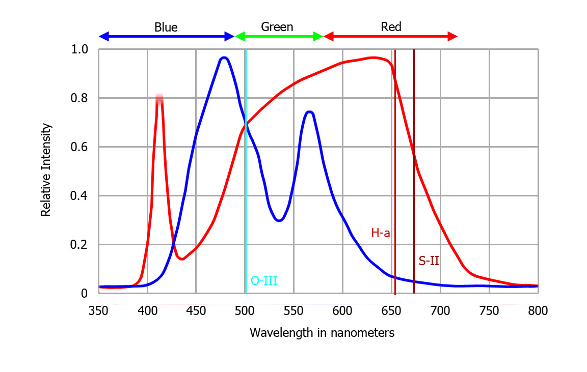
The chart below shows the spectrums of two specific samples of white LED (in red) and white EL panel (in blue). The approximate range of red, green, and blue bands are shown at the top, and the spectral lines for O-III, H-a, and S-II are shown with vertical lines within the graph. The particular LED spectrum shown is not typical. For most ‘white’ LEDs the O-III spectral line is near the lowest intensity output between the blue LED and the red/green phosphor.
When using a one-shot color camera the biggest issue with a white LED as a flat light source is that you want the light to produce roughly equal levels in the R, G, and B channels. It doesn’t matter that the blue channel is a narrowband signal, while the red and green are not. And it is almost the same situation when using a monochrome camera with RGB filters. The only difference is that the RGB filters typically used have sharp cut-offs at the low and high ends of their passband, which can result in a slightly different white balance as compared to a one-shot color camera, which uses more conventional filters that roll of gradually, and overlap between the three color channels.
Where things get more difficult is with narrowband filters. The 3 narrowband filters that are used almost universally are hydrogen-alpha (H-a), oxygen-3 (O-III), and sulfur-2 (S-II). H-a and S-II are both deep red, but significantly different in wavelength. O-III is cyan (blue-green). The typical ‘white’ EL panel produces light containing plenty of signal in the O-III band, but almost none in either H-a or S-II. The typical white LED, on the other hand, provides adequate illumination through H-a and S-II filters, but the O-III band falls right in the gap between the narrowband blue and the near end of the red-green phosphor, so the brightness is very low through an O-III filter. It’s also true that although H-a and S-II filters pass a reasonable amount of light from a white LED, this portion of the spectrum usually has a steep downward slope (toward the red end), so the S-II signal, being a deeper red than H-a, is usually much dimmer than the H-a. This is typically not a big problem because the exposures for H-a and S-II flat frames are separate, so either the exposure duration or the LED brightness can be adjusted to match the brightness. Getting a similar level of exposure in the O-III band requires careful selection of the LED characteristics, but suitable devices are available. I have identified one part in particular that provides similar illumination levels for the narrowband filters, while also being reasonably well white-balanced for RGB filters.
So why have I presented all this esoteric information? Stay tuned for my next blog post to find out!